
A nacelle cutaway — hub, shaft, gearbox, generator, yaw bearing, all on one drivetrain — from one prompt. Engineering is cutaway country, and cutaways are what AI drafting does best: big machines, named components, clean section views. Here are 20 physics and engineering prompts with labels and verify notes.
Open the engineering presets · Full workflow · All 30 examples
One honest boundary first: this works for schematic engineering — machines explained, mechanisms named, energy flows traced. It does not work for exact engineering: real circuit schematics, dimensioned drawings, anything where geometry encodes numbers. For those, generate the explanatory picture, then draw the exact one in a real tool.
Cutaways and machines
1. Wind turbine nacelle
A nacelle cutaway along the drivetrain: rotor hub receiving blade loads, main
shaft, gearbox stepping up speed, generator, and converter cabinet behind, with
the yaw bearing at the tower interface. Label "ROTOR HUB", "MAIN SHAFT", "GEARBOX",
"GENERATOR", "YAW BEARING". Title: "WHAT'S IN THE NOSE".
Verify: power flows hub → shaft → gearbox → generator (speed steps up, torque down); yaw is rotation of the whole nacelle, not the blades.
2. Fuel cell stack
A fuel-cell stack cutaway: repeating membrane-electrode-assemblies and bipolar
plates, hydrogen entering the anode channel, oxygen the cathode channel, protons
crossing the membrane, and electrons forced through an external circuit lighting
a bulb. Label "MEA", "BIPOLAR PLATE", "ANODE", "CATHODE", "EXTERNAL CIRCUIT".
Title: "STACK ANATOMY".
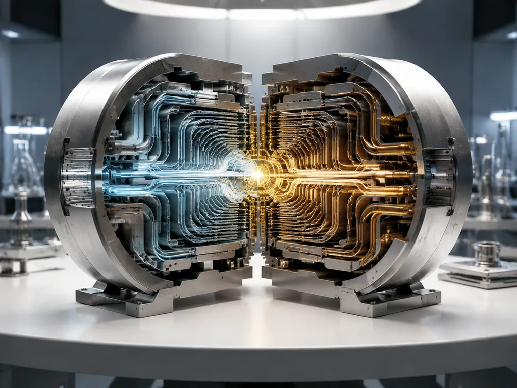
Verify: protons cross the membrane, electrons cannot — that's the whole figure; H₂ in at the anode, O₂ at the cathode.
3. Turbofan engine cutaway
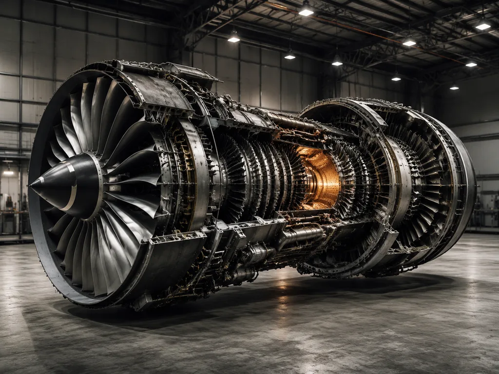
A turbofan engine cutaway from intake to exhaust: fan, low-pressure and
high-pressure compressors, combustion chamber, turbines, and nozzle, with airflow
paths split into bypass and core. Label "FAN", "COMPRESSOR", "COMBUSTOR",
"TURBINE", "BYPASS". Title: "SUCK, SQUEEZE, BANG, BLOW".
Verify: the bypass duct routes around the core; combustion happens between compressor and turbine.
4. Bicycle drivetrain
A mechanical figure of a bicycle drivetrain: crankset with chainrings, chain
wrapping the rear cassette, rear derailleur cage with jockey wheels, and a
gear-ratio calculation inset comparing two chainring-cog pairs.
Label "CHAINRING", "CASSETTE", "DERAILLEUR", "JOCKEY WHEEL".
Title: "THE DRIVE LINE".
Verify: the chain's upper run is under tension (it pulls); ratio inset must show teeth counts that divide correctly.
Materials
5. Carbon fiber laminate
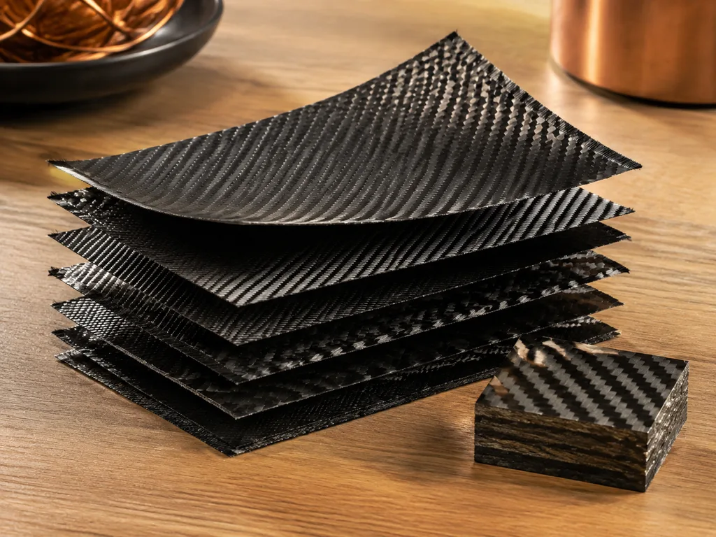
An exploded view of a carbon-fiber composite laminate: stacked plies at
alternating zero and ninety degree orientations, an inset of one woven ply, and a
side view of the cured stack with a magnified fiber-matrix interface.
Label "PLY", "WEAVE", "MATRIX", "INTERFACE". Title: "PLY BY PLY".
6. Carbon nanotube chirality
A materials figure of carbon nanotubes: a rolled graphene sheet showing how the
roll angle sets the tube type, three resulting tubes marked as metallic or
semiconducting, and a bundled rope of parallel tubes. Label "ROLL ANGLE",
"METALLIC", "SEMICONDUCTING", "BUNDLE". Title: "CHIRALITY RULES".
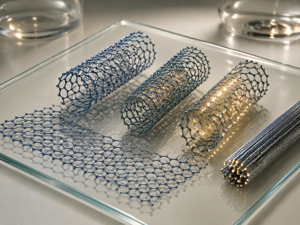
Verify: chirality maps to the roll direction on the sheet — the marked tubes should correspond to the drawn angles.
Forces and mechanisms
7. Free-body diagram, block on incline
A physics free-body diagram: a block on a 30-degree incline with three clean
vectors — weight straight down, normal force perpendicular to the surface, and
friction along the surface opposing sliding — plus a small inset resolving weight
into parallel and perpendicular components. Label "WEIGHT", "NORMAL FORCE",
"FRICTION". Title: "FORCES ON AN INCLINE".
Verify: weight points to Earth's center (straight down), not perpendicular to the slope — the most common physics-figure error there is.
8. Gear train
A gear-train figure: driver and driven spur gears meshing with an idler between
them, rotation arrows on each, a ratio annotation, and one gear-tooth mesh inset
showing the involute contact. Label "DRIVER", "IDLER", "DRIVEN", "MESH".
Title: "GEARS IN TRAIN".
Verify: adjacent gears counter-rotate; the idler changes direction but not ratio.
9. Four-stroke engine cycle
A four-panel row of the four-stroke cycle: intake, compression, power, exhaust —
each panel showing piston position, valve state and a motion arrow, with the
crankshaft angle noted beneath. Label "INTAKE", "COMPRESSION", "POWER",
"EXHAUST". Title: "FOUR STROKES".
Verify: intake valve open only on intake, exhaust only on exhaust; spark belongs in the power stroke's start.
Electricity, schematic-style
10. Simple circuit
A simple series circuit diagram in textbook style: battery, switch, resistor and
LED joined by clean right-angle wires, conventional current arrows flowing from
the positive terminal, and a small voltage-label callout at each element.
Label "BATTERY", "SWITCH", "RESISTOR", "LED". Title: "SERIES CIRCUIT".
Verify: the LED symbol must point along current flow; conventional current leaves the positive terminal.
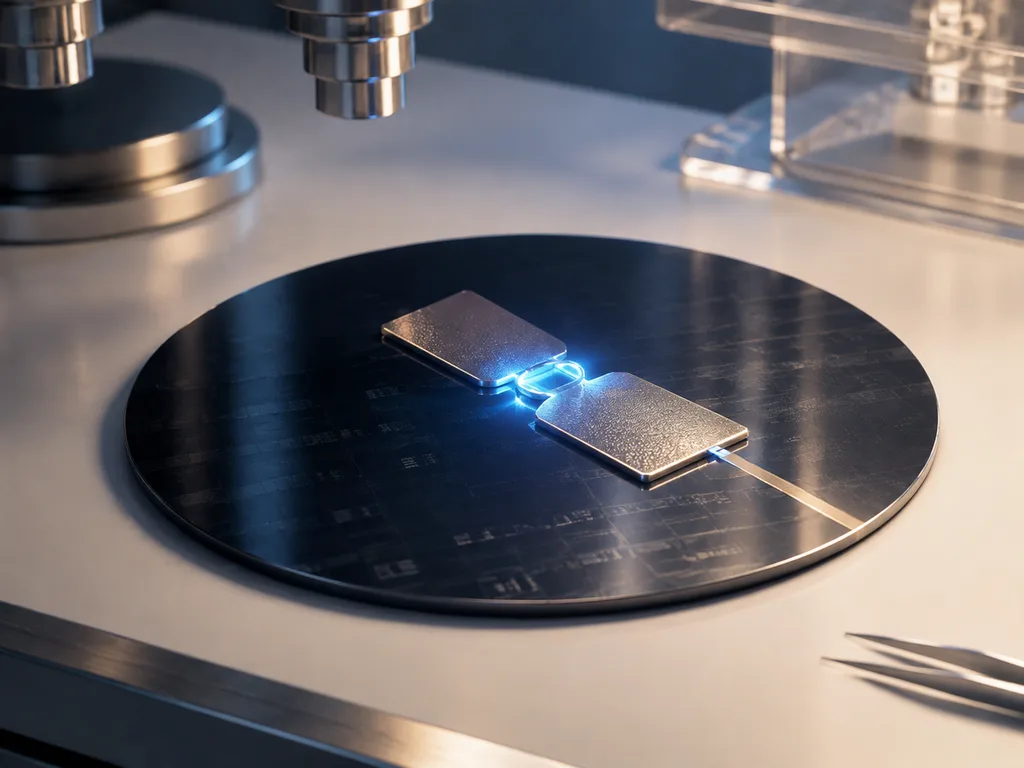
11. Transmon qubit
A superconducting-qubit schematic: cross-shaped capacitor pads, the Josephson
junction as the nonlinear element, readout resonator line coupling to a feedline,
and a chip layout inset with the same features annotated. Label "CAPACITOR",
"JOSEPHSON JUNCTION", "RESONATOR", "FEEDLINE". Title: "ARTIFICIAL ATOM".
Twelve quick variants
| # | Topic | One-line change |
|---|---|---|
| 12 | Pulley systems | "A three-pulley block-and-tackle with rope path and force arrows… Label 'FIXED PULLEY', 'MOVABLE PULLEY', 'MECHANICAL ADVANTAGE'" |
| 13 | Lever classes | "A three-panel row of first, second and third class levers with fulcrum, effort and load… Label each" |
| 14 | Hydraulic press | "Two connected cylinders with pistons of different area, incompressible fluid between… Label 'SMALL PISTON', 'LARGE PISTON', 'PRESSURE'" |
| 15 | Electromagnetic induction | "A magnet moving into a coil with the induced current direction and field lines… Label 'MAGNET', 'COIL', 'INDUCED CURRENT'" |
| 16 | Convex lens optics | "A ray diagram through a convex lens with object beyond focal point, three principal rays… Label 'FOCAL POINT', 'IMAGE', 'OPTICAL AXIS'" |
| 17 | Projectile motion | "A projectile arc with velocity vectors decomposed at three points… Label 'VX', 'VY', 'TRAJECTORY'" |
| 18 | Heat exchanger | "A counterflow heat exchanger cutaway with hot and cold streams in adjacent channels… Label 'HOT IN', 'COLD IN', 'COUNTERFLOW'" |
| 19 | Suspension bridge | "A suspension bridge elevation with towers, main cables, hangers and deck… Label 'TOWER', 'MAIN CABLE', 'HANGER', 'DECK'" |
| 20 | Dam cross-section | "A gravity dam cross-section with reservoir, spillway and tailwater… Label 'RESERVOIR', 'SPILLWAY', 'TAILWATER'" |
Scientific review checklist
- [ ] Are all labels spelled correctly?
- [ ] Are all requested components present, in physically correct order?
- [ ] Do force/flow/current arrows show the correct direction?
- [ ] Do mechanisms rotate/translate the way the physics says?
- [ ] Are scales and proportions reasonable (or labeled as not-to-scale)?
- [ ] Has it been checked against a trusted source?
FAQ
Can AI draw real circuit schematics?
No — and it's worth being blunt about it. Generated "circuits" look like circuits and violate schematic conventions the moment you check symbols and connectivity. Use generated figures for the concept (current path, energy flow) and a real schematic tool for anything an engineer will build from. The boundary is drawn the same way in chemistry for structural formulas.
How accurate are machine cutaways?
Component order and spatial relationships, reliably good (hub → shaft → gearbox → generator); exact geometry and clearances, schematic. For teaching "what's inside and why", that's exactly right. For maintenance documentation, it's exactly wrong — that genre needs the manufacturer's drawings.
Why does free-body diagram direction fail so often?
Because "down" is ambiguous on a tilted surface, and the model resolves ambiguity toward the drawing's local geometry — weight perpendicular to the slope is the classic wrong answer that looks tidy. The fix is explicit: "weight pointing straight down toward Earth's center." This is error #4 wearing physics clothes.
Can I use these in teaching labs?
For pre-lab conceptual figures — the setup, the flow, the safety zones — yes, and they draft beautifully. For the measured schematic the students actually wire, use the real tool and keep the AI figure for the whiteboard explanation of why.
Three cutaways that teach the most
The three machine plates worth building first: the wind turbine nacelle (power flow through a drivetrain — hub to generator, speed up, torque down), the turbofan (flow split — bypass versus core), and the four-stroke cycle (state over time — valve logic per stroke). Each exercises a different reading skill: sequence, branching, and timing. Each also fails in a checkable way — reversed power flow, bypass drawn as a dead end, valves open in the wrong stroke — which is what makes them good verification teaching figures too. The full set of machine plates, with prompts and verify notes, is in the examples gallery; the boundary of what not to attempt (real schematics, dimensioned parts) is drawn at the top of this page.
Next
Run these in the engineering presets. Related: chemistry & lab prompts · earth science prompts · errors and fixes.
<!-- scientific-illustration-cluster-links:start -->
Continue through the scientific illustration collection
Create a scientific illustration · Browse the scientific illustration resource hub
Related: 30 Scientific Illustration Examples with Copyable Prompts · 25 Biology Diagram Prompts for Cells, DNA, Photosynthesis and Mitosis
<!-- scientific-illustration-cluster-links:end -->